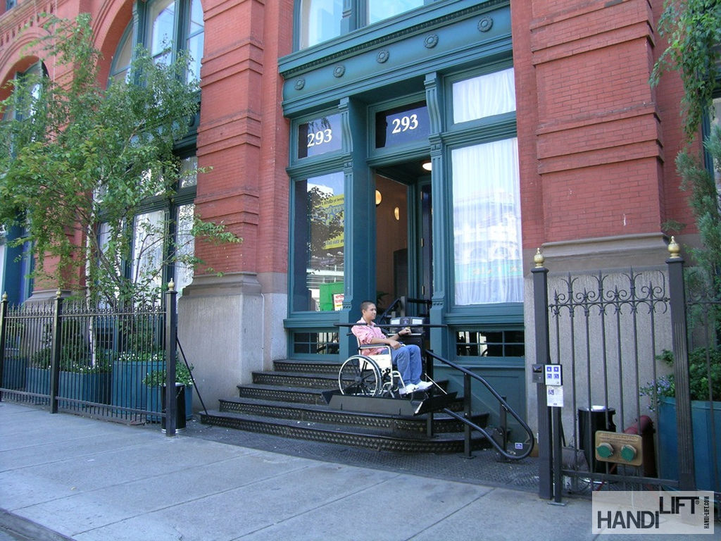
The Puck Building is a turn of the century structure with a cast-iron stairs from the street level to the entry doors. The sidewalk in front of the building has a series of large panels of cast iron and glass bullseyes. These cast iron and glass panels form the sidewalk as well as the ceiling of the cellar space below, which made it possible to use natural light to illuminate the cellar.
The entryway to the building presented a problem in where to locate the drive machine for the accessibility lift. If the drive were on the landing at the top, it would interfere with pedestrian traffic patterns. If it were located on the sidewalk, excessive space would be taken up by the lift platform and drive box. Both options would also be aesthetic concerns from the local Landmarks Commission.
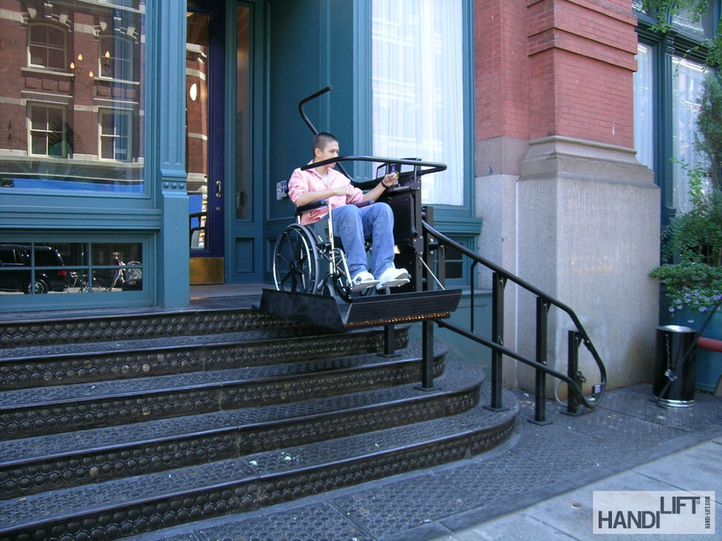
Handi-Lift, Inc's CEO, Doug Boydston and Dean Colucci, project sales engineer, designed a system that would allow the tube structure the lift rides on to make a 90-degree turn at the top of the stairs and penetrate the building wall. This would allow the driving machine to be located inside the building, thus protecting the drive from the weather and solving the aesthetic landmark issue. The support towers for the tubes were mounted through the staircase to steel supports in the cellar, which provided adequate support. Where the towers had to traverse the cast iron and glass, there were serious concerns as to whether the panels were of sufficient strength.
Handi-Lift worked with the architect, Patrick Hebert of Vincent Benic Architects, to design a system to support the lift from beneath the sidewalk. The architects gave Handi-Lift a detailed layout of the space beneath the sidewalk, which the contractor turned into fully dimensioned shop drawings. Polteam Renovation Corp., the general contractor, then used the drawings to locate a structural steel support system designed by the architect that the lift towers could be fastened to. At the appropriate locations marked out by Handi-Lift, Polteam core drilled the sidewalk to allow the lift support tubes to pass through the sidewalk and be welded to the steel support system beneath. After the support towers were welded, escutcheon plates were installed an caulked in place with silicone.
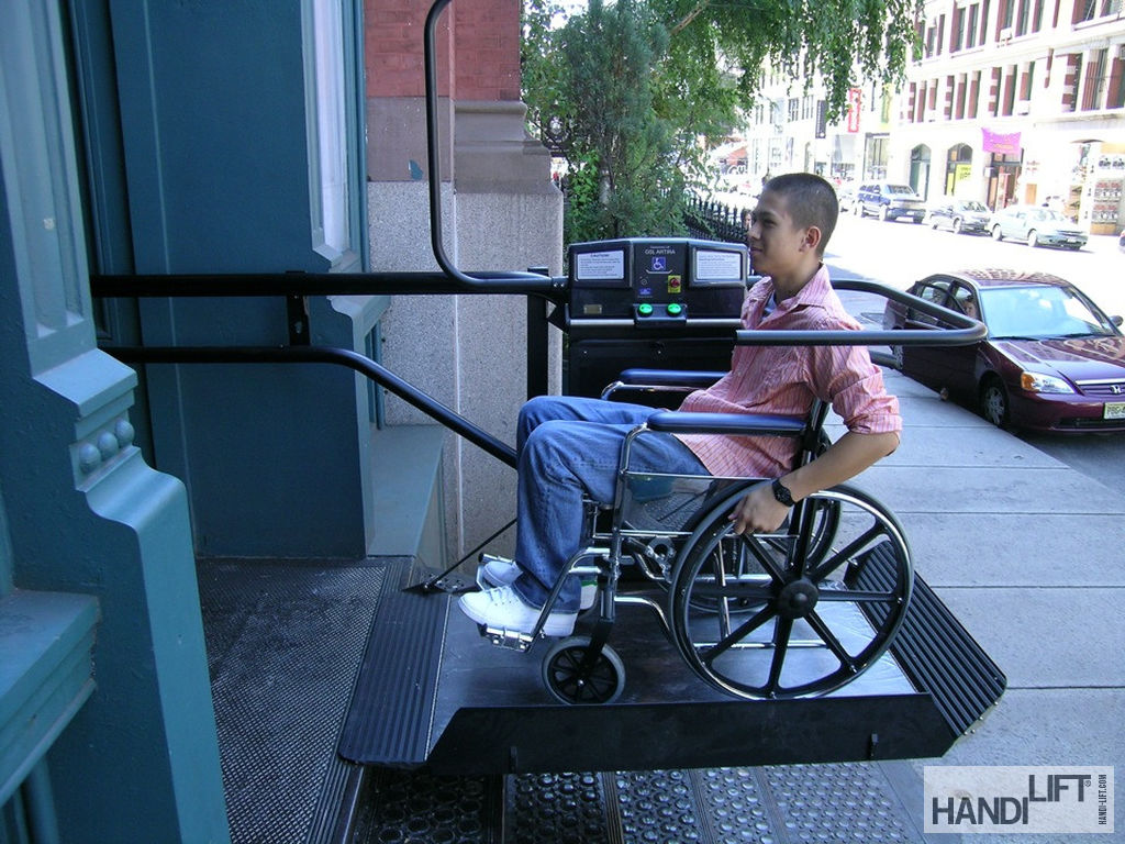
The entire support system and hardware were fabricated out of stainless steel and powder-coat finished in black to match the existing staircase and railing. The lift platform stores at the bottom and folds up against the railing, minimizing any visual impact. The tubes travel along the sidewalk rail, then turn and go up the side of the stairs. The lift discharges the passenger at the top step, while the tubes continue and turn 90 degrees into the wall.
The system operates via a VVVF motor-controlled gearbox and drive cog located in the drive cabinet. The stainless-steel tubes contain a haul cable with insulated balls that travel through the drive box and over a drive cog. The upper tube is slotted on the underside to allow the lift platform to be attached to the cable. Thus, when the drive cog turns, it in effect becomes a sprocket, and the cable with the balls becomes a chain. The lift is moved along with the cable. The cable is comprised of two pieces spliced together to make a continuous piece. The upper cable is connected to the lift; the lower cable contains swaged-on, conical shaped pieces that allow the safety dogs to engage should there be a broken cable.
The controls are dedicated micro-processor based and obtain location information from an absolute encoder, which is programmed to count pulses from landing to landing as well as to each slowdown point. The system is powered by 24VDC sent down the cable, with the tube itself being ground. The serial communications with the lift platform are superimposed on the cable also.
The lift carriage has two sets of carriages on a swivel mount with the rollers it rides on, and upthrust rollers to precent derailing. With the movable carriages, precise computer-bent tubes and the cable drive system, the Artira is capable of navigating helical bents, landings in mid-stair as well as doing a 180-degree turn to park out of the way.